WELL it's been about 10 days since the last post, mostly due to the fact that I got the flu. It sucked. I'm still not completely over it, but whatever. Luckily work didn't completely stop. Between the extremely talented Jesse Fast from Fix it Fast Auto Care and my other buddies John Welsh and Brian Hopkins, they got a lot of stuff done while I just supervised with my hot tea in hand!
Before we get into it, here's an updated pic!
As you can see we're starting to have a front end! We started right before I got sick, here's what we did:
1. So first thing we did was cut the driver's side frame rail. We did this so we could remove the rest of the front end. We decided we were going to replace both frame rails at least 25 inches back, both of the front fender aprons, and the entire front radiator support.
We cut the driver's side frame rail back the same distance we cut the passenger side back (22.5" from the end of the outter frame rail). This ended up not mattering because we decided to go a little further later, but we will get to that. We also had to make a quick cut at the top between the two fender aprons:
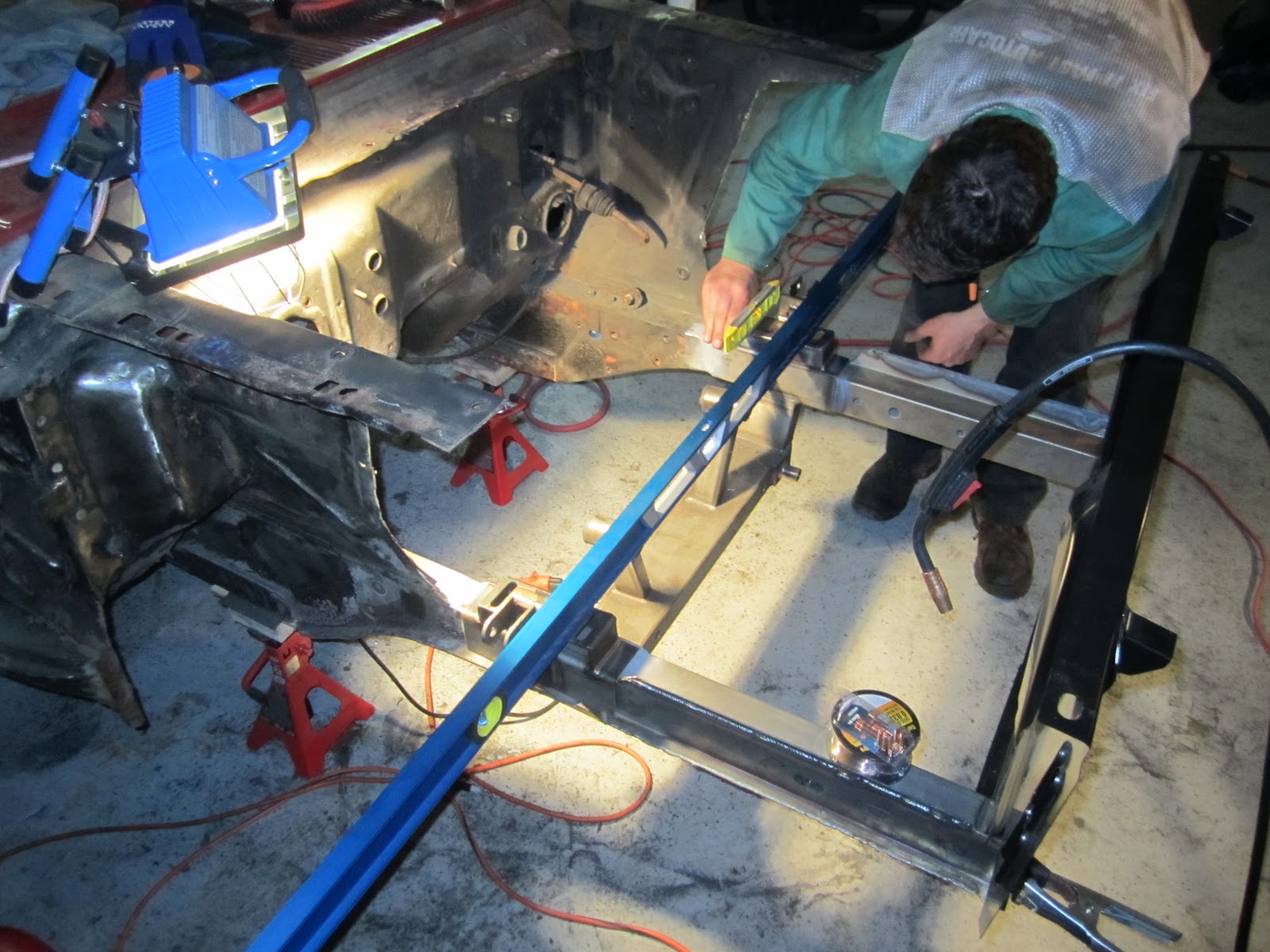
2. We went back AND LEVELED THE CAR AGAIN. Seriously guys, do this often. Measure 400x, cut once. Why let any mistakes get made? The more we measure, the surer we are. In the picture directly above you can see we made a datum line with wood along the floor. On the previous post we posted a link to the measurements from the datum line you must use to level the car. We also bought a 6 foot level and leveled from every possible angle we could over and over again.
3. Next we had to finish the disassembly. Yes, there was still a couple things to be done.
Removing the Heater Assembly.
a. Cut the hoses at the firewall (they will be replaced anyway) these hoses run from the engines coolant system to the heater core inside the car.
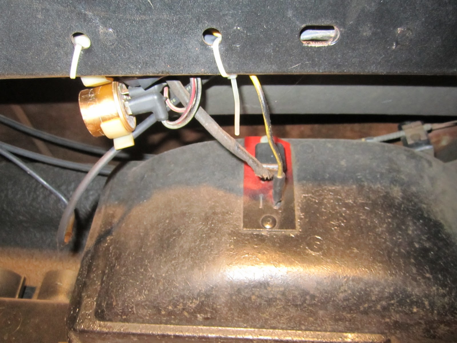
b. Disconnect the 2 wire harnesses from the heater box inside the car:
c. Remove the bolt from the main hanger found above the door handle on the heater assembly (NOTE: hanger has a gray ground wire to it, mine was cut, and mine also had 2 nuts behind the bolt... major pain in the ass to remove):
d. Remove the defroster tension cable from the defroster unit (runs to the heater controls):
e. Remove the 4 bolts from the heater fan motor (in the engine bay):
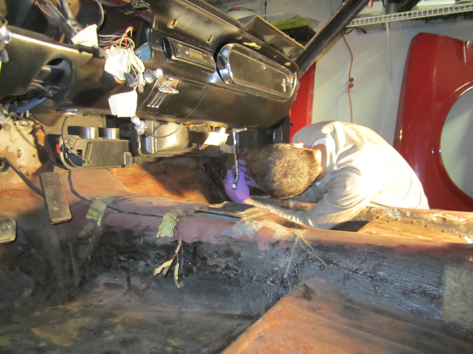
f. Once the heater assembly drops to the floor you can access the remaining 2 tension cables for the rest of the heater controls. Remove them AND BE SURE to label everything.
4. Removing the Window Chrome Strips (and Drip Rail Chrome Strips)
First thing you want to do is remove the phillips screws that hold the inner rails on, there are 10 on each. Plus there's a little clip for the molding.
After that these basically come off with some force, TRY NOT TO DESTROY THEM... apparently they don't make reproductions of the inside ones (eeeek)
Once we finished there we scrapped all the old seal out from the inside of the drip rails.
5. Remove the Rear Brake line and Fuel Line
In my case both need to be replaced (for the larger engine and larger disc brakes). But still... be gentle, right John?
Mostly it's held up with clips that need to be pryed open. In the front there's a couple bolted clips as well.
6. Remove the Gas Pedal
To do this there's just 2 bolts in the engine bay that hold the clips in place that hold the gas pedal in place. Then in the inside of the car there's a single screw on the back of the gas pedal. Remove that and slide it out.
7. Remove the Speedometer cable
At this point it was just hanging there and in the way. Pull it out... (normally connected from transmission to the instrument bezel).
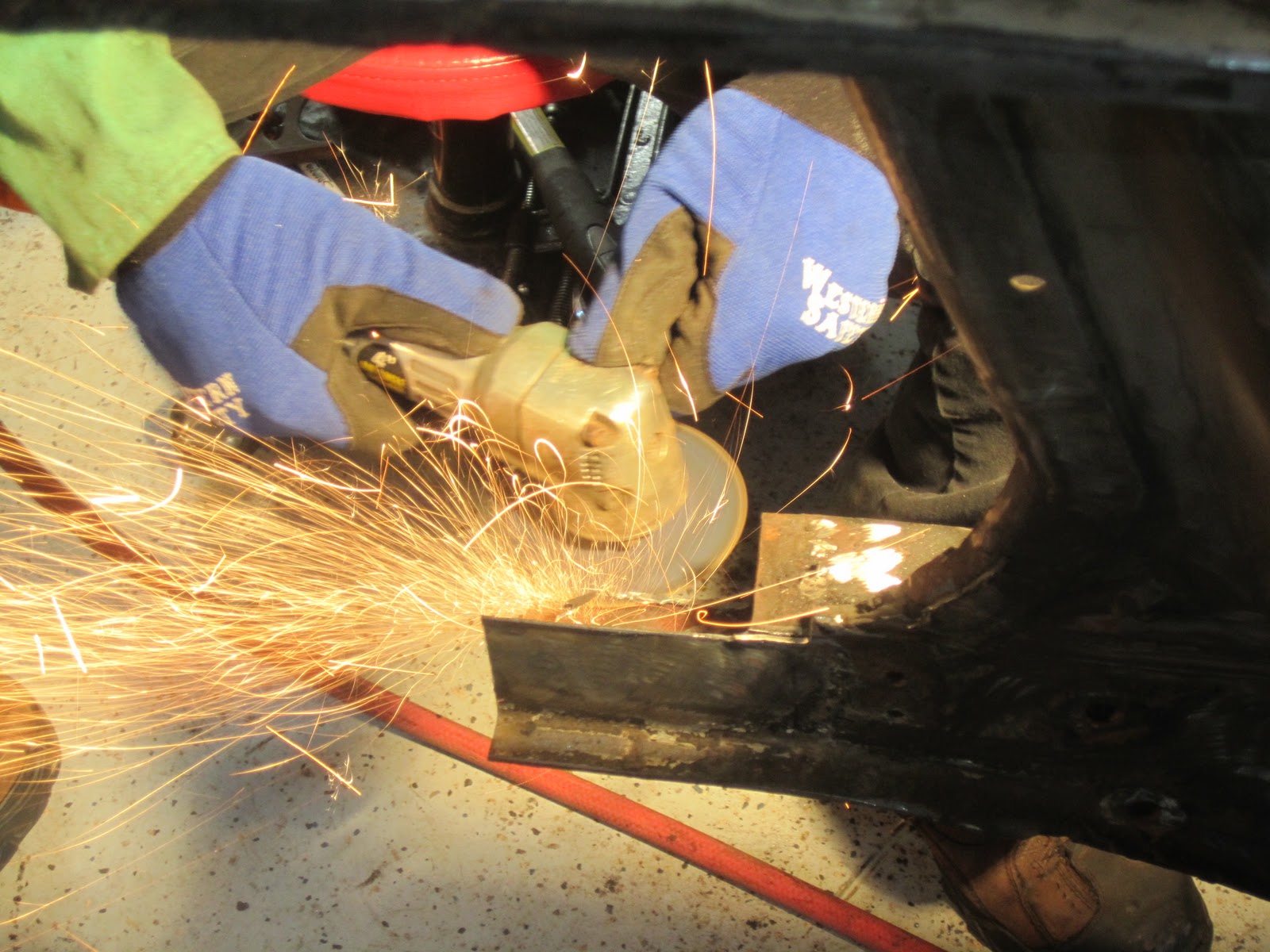
At this point I got super sick and nothing happened for a few days. Until Jesse Fast from Fix it Fast Auto Care came and helped me out. The man is a God send. Here's what the process looked like...
I don't want to go into too much detail about the exact measurements we used BECAUSE EVERYONE WILL DO THIS DIFFERENTLY. The key to this process is to cut back as far as you need to to get rid of all the rust that's eating through your frame rails. Rust is like a cancer and it WILL SPREAD. So we went back pretty far and did what we had to do to make the new frame rail extensions fit.
We used .030 welding wire, gas shielded. You must must must make sure everything is 100% level and size correct. Use existing measurements, factory manuals, and the internet forums for reference.
Also what we did was try and make our repairs inside the center of where our new cross member is welded into place. The cross member is 9 inches wide and acts as a coupling around the frame rails. You can't see it yet, but there are tops to those new cross members and once they are welded into place it will make a complete seal around the areas of the frame rails where the patches are making a complete coupling around all repairs. This is ideal, keep your patches hidden and double patched if possible. We may also in the future add more strength by putting in horizontal cross members at the tops of the engine bay as well as triangulation in the front. Stay tuned!