Monday, October 24, 2011

Days 58 - 66: More cleaning/scraping/grinding, welding the floor pans, and the car claims another hand!

So for the past 8 days we've been on and off cleaning the car, this is taking forever. I guarantee you if i ever do another one of these I'm shipping it out to be blasted because this is just ridiculous.

We got most of the seams around the floor pan done. Basically at some point someone put in new floor pans and instead of welding it, riveted and bolted it into place. We wanted to get rid of all the rivets and bolts on this unibody and make sure that everything is welded instead.

Here's some pictures of that process:

The first thing we did was disassemble the upper part of the front suspension that we dry built. Since the lower A arm and strut are assembled, leveled, and lubed properly, we left them in place and wrapped them in foil so they wouldn't get damaged:


After that we spent some time working on cleaning the engine bay up and everything related to the floor pan seams:


We removed the "z clutch bar" bracket..


We also started to remove the rear torque box that's rusted out, we're gonna be replacing the entire thing on both sides. Basically creating a brand new front and rear and we'll hold them together with brand new frame rail connectors. This ensure that's all the weight of the car is being held up with all new suspension, all new rear, and all new frame rails and torque boxes, properly welded to the rest of the uni-body. No corner cutting here (well, except where we physically literally cut out the corners...)


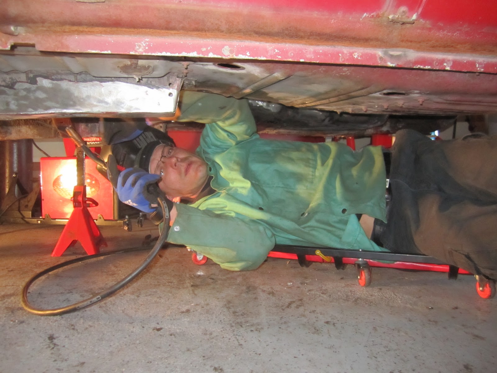
Then Jesse came and welded some floor pans! Oh but about 30 seconds into hitting a spot with the grind wheel to clean...


The car claimed another piece of finger... haha

Here's what he got done after we wrapped that up:


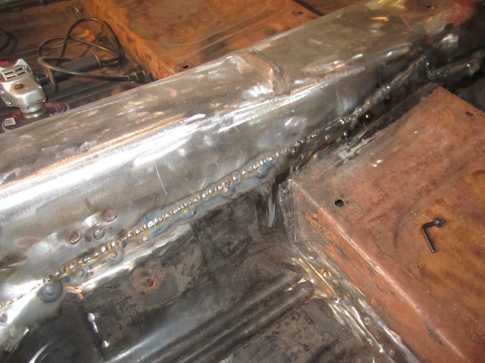
After he started to weld the seams he drilled out all the old rivets and bolts and then welded the holes close. This week we will be grinding down his welds so once it's painted it will all look flush! No more frankenstein looking bolts everywhere!


That's it for now! More to come...

Monday, October 17, 2011

Day 57 - Finish welding crossmember, modify steering column and build that front suspension!

OK so on Saturday Jesse came over and finished welding the front cross member and rad support. I had to help my dad sand and stain my mom's deck so I was busy during that, but then afterwards we watched the Rod and Custom "how to" DVD again and got started on the steering column and front suspension. This is just a dry build, we're still going to remove the suspension again so that we can paint underneath. The frame rails are being painted with por-15 rust preventative paint. Once that paint is applied we will rebuild the front suspension and steering and then it will be final!

1. Modifying the steering column:

a. Cut the old steering shaft from the steering box (it's a fixed shaft)

b. Put the shaft back in the column at it's original position and take a measurement from the top of the shaft to the top of the column.


c. Place the shaft next to the column at that same length.


d. The splice joint needs to be at a minimum of 1" inside the column, the splice joint is 4" long total, so you want 2" of extension and 2" of original shaft inside the splice (with the splice itself at least 1" up into the column).


e. Weld the splice joint together to extension and shaft.


f. Install bearing retainer, weld into place.


g. Slide black locking collar over, alan wrench on (prevents the shaft from moving up and down column).


OK so with the steering column modified and ready to go we set it aside. We're not ready to install it yet, still have a lot more cleaning and grinding to do, plus painting!

Next we started our dry run of installing the suspension and steering.

This is a pretty detailed process. The first thing we did was install the lower A-arm (control arm).

There's a long bolt that goes through the cross member, coat the shit out of this was anti-seize compound.


Then what you want to do is install it and make it level with the cross member by using a clamped straight edge underneath the cross member. This is needed to position the sway bar so that you can weld the sway bar brackets onto the frame rails. Here's what that process looked like:


Note: Cover any painted items in foil anytime you're welding near them.


With the sway bar bracket in place, we proceeded to built the upper a-arm (control arm), put the tie rod ends on, and put the spindle in place to make sure it all fit, and guess what:


Boo ya! Oh happy day!